- Equipment code : CFIHOS-30000838

Description
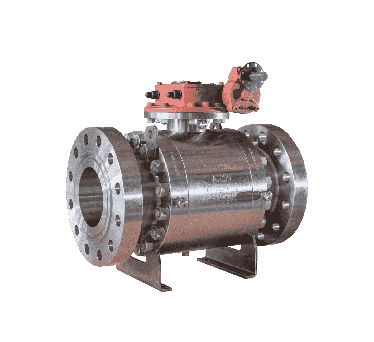
PPRODUCT RANGE:
Sizes: NPS 2 to NPS 60
Pressure Range: Class 150 to Class 2500
Flange Connection: RF, FF, RTJ
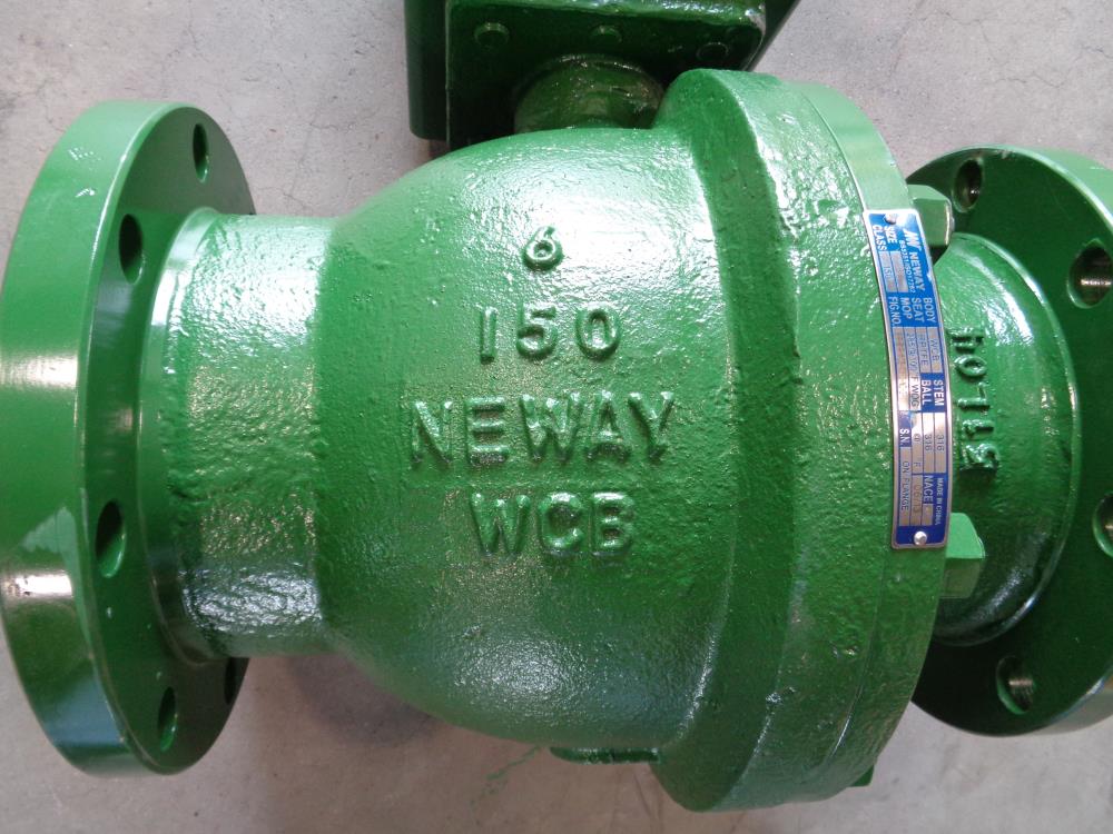
MATERIALS:
Casting: (A216 WCB, A351 CF3, CF8, CF3M, CF8M, A995 4A, 5A, A352 LCB, LCC, LC2) Monel, Inconel, Hastelloy,UB6
STANDARD
Design & manufacture API 600, ISO 10434, API 6D, API 603
Face-to-face ASME B16.10
End Connection ASME B16.5, ASME B16.47, MSS SP-44 (NPS 22 Only)
BW End: ASME B16.25
Socked Welded End: ASME B16.11
Test & inspection API 598
Also available per NACE MR-0175, NACE MR-0103, ISO 15848
Other PMI, UT, RT, PT, MT
Design Features:
Full or Reduced Bore
RF, RTJ, or BW
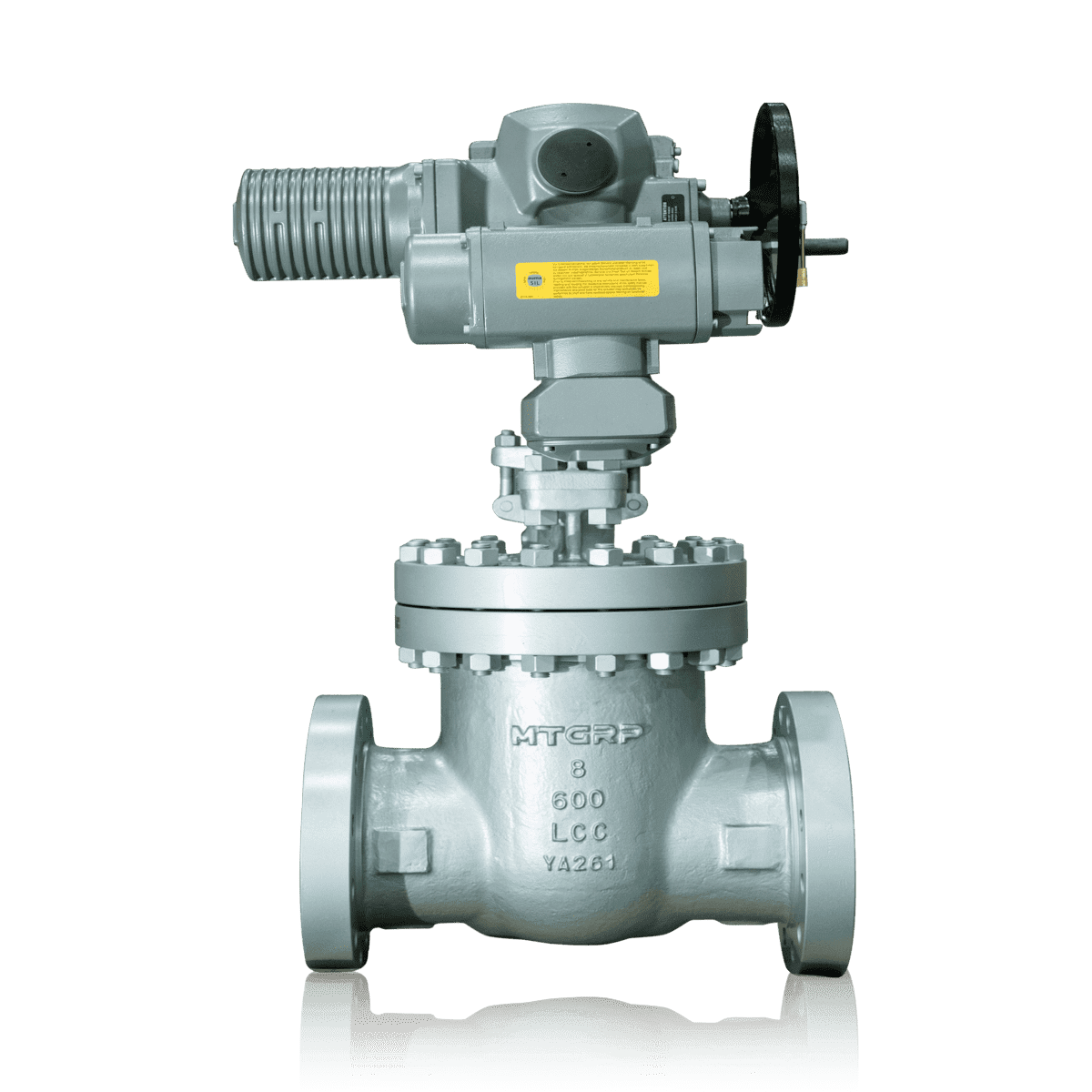
Outside Screw & Yoke (OS&Y), rising stem
Bolted Bonnet or Pressure Seal Bonnet
Flexible or Solid Wedge
Renewable seat rings
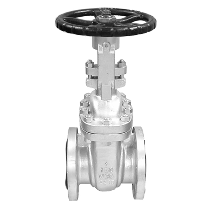
Flange gate valve is a gate valve with flange connection, this connection method is the most common. Flange gate valves are stable and reliable when used in pipelines, so flange gate valves are often used in high-pressure pipelines.
When the flange gate valve is closed, the sealing surface can only rely on the medium pressure to seal, that is, rely on the medium pressure to press the sealing surface of the gate to the valve seat on the other side to ensure the sealing of the sealing surface, which is self-sealing. Most gate valves use forced sealing, that is, when the valve is closed, the gate must be forced against the seat by external force to ensure the sealing of the sealing surface.
The gate of the gate valve moves linearly with the valve stem, which is called the lifting stem gate valve (also called the rising stem gate valve). Usually there is a trapezoidal thread on the lifting rod. Through the nut on the top of the valve and the guide groove on the valve body, the rotary motion is changed to linear motion, that is, the operating torque is turned into operating thrust.
When the valve is opened, when the lifting height of the gate is equal to 1:1 times the valve diameter, the fluid passage is completely unblocked, but this position cannot be monitored during operation. In actual use, the apex of the valve stem is used as a mark, that is, the position where it cannot be opened, as its fully open position. In order to take into account the locking phenomenon due to temperature changes, the valve is usually opened to the apex position and then rewinded by 1/2 to 1 turn as the fully open valve position. Therefore, the fully open position of the valve is determined by the position of the gate (ie stroke>.
In some gate valves, the stem nut is set on the gate, and the rotation of the handwheel drives the rotation of the valve stem to lift the gate. This kind of valve is called a rotating stem gate valve or a dark stem gate valve.
Installation of flange gate valve:
1. Check the inside of the valve cavity and the sealing surface before installation, and no dirt or sand particles are allowed to adhere;
2. The bolts of each connection part shall be evenly tightened;
3. Check the packing parts to be pressed tightly, not only to ensure the tightness of the packing, but also to ensure the flexible opening of the gate;
4. Before installing the valve, the user must check the valve model, connection size and pay attention to the flow direction of the medium to ensure consistency with the valve requirements;
5. When installing the valve, the user must reserve the necessary space for the valve drive;
6. The wiring of the drive device must be carried out according to the wiring diagram;
7. The gate valve must be maintained regularly, and no collision or squeeze is allowed to avoid affecting the seal.
General Terms
- ReflowX and the seller retain the right to evaluate and approve offers.
- Buyers should verify quantities and conditions upon delivery.
- After successful engagement, both buyer and seller manage communication for payment terms and delivery schedule.
- All parties agree to adhere to ReflowX Terms and Conditions in transactions.
- Buyers can request value-added services such as pre-purchase inspections, Expediting & Delivery Services through ReflowX. Contact us!


0
Ball valve
Selling Price
$180
United Arab Emirates

0
Ball valve
Selling Price
$149
United Arab Emirates

0
Ball valve
Selling Price
$313
United Arab Emirates

0
Ball valve
Selling Price
$501
United Arab Emirates
0
Ball valve
Selling Price
$1392
United Arab Emirates
0
Ball valve
Selling Price
$198
United Arab Emirates

0
Ball valve
Selling Price
$379
United Arab Emirates

0
Ball valve
Selling Price
$578
United Arab Emirates


0
Ball valve
Selling Price
$1099
United Arab Emirates

0
Ball valve
Selling Price
$3035
United Arab Emirates


0
Ball valve
Selling Price
$1114
United Arab Emirates

0
Ball valve
Selling Price
$132
United Arab Emirates

0
Ball valve
Selling Price
$258
United Arab Emirates

0
Ball valve
Selling Price
$349
United Arab Emirates

0
Ball valve
Selling Price
$627
United Arab Emirates

0
Ball valve
Selling Price
$1118
United Arab Emirates

0
Ball valve
Selling Price
$273
United Arab Emirates

0
Ball valve
Selling Price
$580
United Arab Emirates

0
Ball valve
Selling Price
$337
United Arab Emirates

0
Ball valve
Selling Price
$585
United Arab Emirates

0
Ball valve
Selling Price
$828
United Arab Emirates

0
Ball valve
Selling Price
$1304
United Arab Emirates
0
Ball valve
Selling Price
$2070
United Arab Emirates

0
Ball valve
Selling Price
$4509
United Arab Emirates

0
Ball valve
Selling Price
$1065
United Arab Emirates

0
Ball valve
Selling Price
$5665
United Arab Emirates

0
Ball valve
Selling Price
$1268
United Arab Emirates

0
Ball valve
Selling Price
$2431
United Arab Emirates


.jpg)


0
Butterfly valve
China


Award

